Prefabricated Substation Installation – Frequently Asked Questions

 by changan electric
The unit arrives on site. The crane is scheduled. Your team is ready. But before you start, there are questions that need answers—answers that can mean the difference between a smooth installation and a costly delay.
A Prefabricated Substation can dramatically shorten your project timeline, but the installation details determine long-term reliability. Get the foundation wrong, and the unit settles unevenly. Misjudge the lifting points, and you risk damaging the enclosure. Overlook clearance requirements, and you can’t access breakers for maintenance. Skip the cooling design, and the transformer overheats on the first hot day.
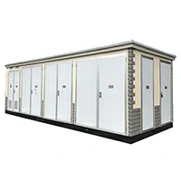
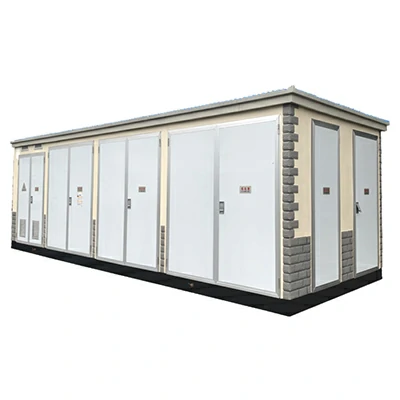
This article answers the most frequently asked questions about prefabricated substation installation—covering foundation requirements, lifting and placement, clearance for operation and maintenance, cable entry and sealing, cooling and ventilation, and grounding system connection. For project site managers and electrical engineers, these are the practical answers you need before the crane arrives. Chang‘an Electric’s YBM EU Type Prefabricated Compact Substation is designed with these installation considerations in mind, but even the best equipment needs proper installation to perform as intended.
What Foundation Type Is Required?
The foundation is the first—and most critical—step in your installation. Get it wrong, and everything else suffers.
Concrete Strip vs. Solid Slab Foundation
The choice between a concrete strip foundation and a solid slab depends on your site conditions and the substation weight. A strip foundation (continuous footings around the perimeter) works for most applications with stable soil conditions. A solid slab provides more even load distribution and is recommended for sites with poor soil bearing capacity or when the substation weight exceeds 15 tons.
Load Capacity Calculation
The foundation must support the weight of the substation equipment plus any live loads (maintenance personnel, temporary equipment). For the YBM EU Type substation, the transformer and switchgear combination typically weighs between 5 and 15 tons depending on the configuration. Add a safety factor of 1.5 to account for dynamic loads during installation.
Embedded Channels for Anchoring
Pre-embedded steel channels must be placed with precision—typically within ±2mm of the specified positions. These channels anchor the substation to the foundation. If they‘re misaligned, you’ll struggle to bolt the unit down securely. Use a laser level or theodolite during concrete pouring to verify channel positions.
Drainage Slope Requirement
The foundation should have a slight slope (1-2%) away from the substation to prevent water pooling around the enclosure. Standing water accelerates corrosion of the metal enclosure and can seep into cable trenches. Include a drainage channel or French drain around the perimeter.
How to Lift and Place the Substation Without Damage
Lifting a prefabricated substation is a high-risk operation. One mistake can damage the enclosure or worse.
Locating Lifting Lugs – Use Only Designated Points
Every prefabricated substation has designated lifting lugs or lifting points. Use only these points. Never attach slings to the enclosure corners, ventilation louvers, or cable entry boxes. The lifting lugs are engineered to handle the full weight of the unit with an appropriate safety margin.
Spreader Bar Necessity
A spreader bar is not optional—it‘s essential. Without one, the slings squeeze the enclosure sides, potentially denting or distorting the panels. A spreader bar keeps the slings vertical, distributing the load evenly across the lifting lugs. For units over 5 tons, use a spreader bar with a capacity rating that exceeds the substation weight.
Avoid Overturning – Center of Gravity Awareness
The center of gravity of a prefabricated substation is not necessarily at its geometric center. The transformer is the heaviest component, and it’s usually located off-center within the enclosure. Check the lifting diagram provided by the manufacturer to locate the center of gravity. If you lift without accounting for this, the unit can tilt dangerously during the lift. Chang‘an Electric provides lifting diagrams with each YBM EU Type substation to guide proper rigging.
Minimum Clearance for Operation and Maintenance
Once the substation is in place, you need room to work. Clearance requirements are often overlooked—until someone needs to open a door or pull out a breaker.
Front Clearance – 1200mm Minimum
The front of the substation (where the low-voltage and high-voltage doors are located) needs at least 1200mm of clear space. This allows operators to open doors fully, withdraw circuit breakers, and access control panels. For units with draw-out circuit breakers, add another 500mm to accommodate the breaker on its extension rails.
Rear Access for Cable Termination
Many prefabricated substations require rear access for cable termination and maintenance. The YBM EU Type substation typically has cable entry from the bottom, but some configurations require rear access for termination work. Check your specific unit’s layout. If rear access is required, maintain at least 800mm clearance.
Top Clearance for Ventilation
The top of the substation has ventilation louvers or forced ventilation fans. These need unobstructed airflow. Maintain at least 500mm clearance above the unit to allow hot air to escape. If the substation is installed under a canopy or inside a building, ensure the overhead clearance doesn‘t trap heat.
Cable Entry and Sealing Methods
Cables are the lifeline of your substation. How they enter and how they’re sealed affects both safety and reliability.
Bottom Entry Through Cable Trenches – The Most Common Method
Bottom entry through a cable trench or cable basement is the most common configuration for prefabricated substations. The YBM EU Type substation is designed with bottom cable entry as the standard. The trench should be deep enough to accommodate the cable bending radius—typically 600-800mm. Run the trench under the substation foundation before the unit is placed.
Gland Plates and Firestop – The Importance of Fireproof Sealing
Each cable entry point must be sealed with a gland plate and firestop material. This serves two purposes: it prevents water ingress through the cable opening, and it maintains the fire rating of the substation enclosure. Use intumescent firestop seals that expand when exposed to heat, closing off the opening in the event of a fire.
Shielding Against Rodents – Stainless Steel Mesh
Rodents can enter through cable openings and damage insulation. Install stainless steel mesh (with openings no larger than 6mm) over cable entry points before applying the firestop. This provides a physical barrier that rodents can‘t chew through. The mesh should be secured to the gland plate with proper fasteners.
Cooling and Ventilation in Summer
Prefabricated substations are compact, and compact means heat builds up fast. Without proper cooling, transformer life is significantly shortened.
Natural Convection Louvers – Sufficient Area Required
The substation enclosure includes louvers for natural convection cooling. These louvers need sufficient open area to allow hot air to escape. As a rule of thumb, the louver area should be at least 5% of the enclosure footprint for each 100kVA of transformer capacity. For a 800kVA unit, that‘s significant open area. Keep louvers clear of debris and vegetation.
Forced Ventilation with Thermostat – Set at 40°C
Most prefabricated substations include forced ventilation fans triggered by a thermostat. Set the thermostat to activate at 40°C. This ensures the fans run when needed—but not continuously, which reduces fan life. The YBM EU Type substation is designed with ventilation louvers and can be equipped with forced ventilation as needed.
Avoiding Recirculation – Inlet and Outlet Must Not Short-Circuit
The inlet and outlet vents must be positioned so that hot exhaust air isn‘t drawn back into the inlet. This “recirculation” makes the cooling system ineffective. Inlet vents should be at the bottom of the enclosure (cooler air enters there) and outlet vents at the top (hot air rises). Keep a minimum horizontal separation of 1 meter between inlet and outlet on the same side.
| Installation Factor | Requirement | Why It Matters |
|---|---|---|
| Foundation Type | Concrete strip or slab | Prevents settling and misalignment |
| Embedded Channels | ±2mm precision | Ensures proper anchoring |
| Front Clearance | 1200mm minimum | Allows breaker access and maintenance |
| Cable Entry | Bottom via trench with firestop | Prevents water ingress and fire spread |
| Ventilation Area | ≥5% footprint per 100kVA | Prevents transformer overheating |
Grounding System Connection
Grounding is non-negotiable for safety and equipment protection.
Main Ground Bus Location – Typically in the Cable Compartment
The main grounding bus is usually located in the cable entry compartment. This is where you connect the substation to the site grounding grid. The bus bar should be clearly labeled and accessible for testing.
Two Separate Ground Connections – Redundancy Required
Safety standards require two separate ground connections for prefabricated substations. This provides redundancy—if one connection fails, the other still maintains the ground path. Use separate grounding conductors run to two different points on the site grounding grid. The YBM EU Type substation is designed with dual ground connection points for compliance with international standards.
Ground Resistance Test – Target Below 1Ω
After installation, measure the ground resistance. The target is less than 1Ω. Higher resistance indicates a poor connection to earth—either the grounding electrodes are insufficient or the connections are faulty. Test before energizing the substation. If the resistance is above 1Ω, add additional grounding electrodes or improve the connections.
Questions Site Managers Ask After Installation
Can I install a prefabricated substation on a rooftop?
Yes, but only after a structural engineer evaluates the roof‘s load-bearing capacity. The combined weight of the substation (up to 15 tons) plus wind and seismic loads can exceed what a standard roof is designed for. If approved, use a steel frame to distribute the load across multiple roof beams. Also ensure the crane can access the roof for placement.
How do I prevent condensation inside the enclosure?
Condensation occurs when warm, moist air enters the enclosure and cools on internal surfaces. Install anti-condensation heaters inside the enclosure—typically 100-200W heaters that run continuously or are thermostatically controlled. These keep the internal temperature above the dew point. Also ensure all cable entries are properly sealed to prevent moist air from entering.
What’s the typical lead time for a custom unit?
For a standard configuration like the YBM EU Type, lead time is typically 6-8 weeks from order confirmation. Custom configurations—with specific transformer ratings, switchgear brands, or special enclosure finishes—can extend this to 10-12 weeks. Plan your project timeline accordingly. Chang‘an Electric offers a response within 24 hours for inquiries.
Is a crane needed if the substation is skid-mounted?
Yes—for almost all models. Even skid-mounted units typically weigh several tons and require a crane for placement. Only the smallest units (under 2 tons) can be moved with a forklift. The YBM EU Type substation, with its transformer and switchgear combination, typically weighs 5-15 tons and requires a crane. Check the unit‘s weight plate before scheduling lifting equipment.
Pre-Installation Checklist for Site Managers
Before the substation arrives, work through this checklist to avoid surprises:
Site Preparation
-
Confirm the transport route has no height restrictions (bridges, power lines, overpasses)
-
Verify the crane can access the installation site with adequate reach and capacity
-
Ensure the concrete foundation has cured for the required 28 days
-
Confirm the foundation bolts or embedded channels are correctly positioned
Equipment and Materials
-
Prepare the crane with appropriate capacity (check the substation weight)
-
Have spreader bars and slings with adequate working load limit
-
Prepare temporary power for internal heaters (if required)
-
Have firestop material, gland plates, and stainless steel mesh ready for cable sealing
Personnel and Documentation
-
Schedule the manufacturer‘s technical representative for first energization
-
Have the lifting diagram and installation manual on site
-
Brief the lifting crew on the center of gravity and designated lifting points
Final Recommendations – Make the First Energization Count
The installation is complete. The cables are connected. The grounding is tested. Now comes the moment of truth: first energization.
Manufacturer Supervision Is Essential
Schedule a manufacturer‘s technical representative to be on site for first energization. They can verify that all connections are correct, that the protection settings are appropriate, and that the unit operates as designed. Chang‘an Electric provides technical support as part of their service offering.
Documentation Is Your Safety Net
Document every step of the installation. Take photos of the foundation, the lifting operation, cable terminations, and grounding connections. Keep records of torque values for bolted connections. This documentation is invaluable for future maintenance and troubleshooting.
Chang‘an Electric manufactures the YBM EU Type Prefabricated Compact Substation, a unit designed for reliable power distribution in demanding environments. The EU type substation is composed of transformers, 10KV ring network switchgear, low-voltage capacitors, low-voltage switches and other main components. It’s equivalent to compactly installing the equipment of a Type III substation in a metal box, making it miniaturized. The noise of EU type substations is comparable to Type III and Type I substations, and the radiation is lower than US type substations because the transformers are placed in metal boxes for shielding. Power distribution automation can be set, combining the advantages of both Type III and Type I substations with the main advantages of American substations. Available with single transformer configurations (500KVA~800KVA) or dual transformer configurations with 8-12 outgoing low-voltage lines, the YBM EU Type is designed for ease of installation and long-term reliability.
A prefabricated substation installation is a significant project, but with proper planning and attention to detail, it can be completed smoothly. Focus on the foundation, use the correct lifting procedure, maintain adequate clearances, seal cable entries properly, ensure cooling airflow, and verify the grounding. With these fundamentals in place, your substation will provide reliable service for decades.
Ready to install your prefabricated substation? Reach out to Chang'an Electric's technical team—they can provide installation manuals, lifting diagrams, and on-site support to ensure a successful first energization.