Ring Main Unit Operating Questions – What Every Site Engineer Should Know

 by changan electric
You’ve been called to a residential substation after a power outage. The fault indicator is blinking. The gas pressure gauge is reading low. The operating handle won’t fit into the earth switch slot. A junior operator is standing there, hand on the mechanism, about to force it. You stop him just in time—then you walk him through the sequence. Load switch first. Cable test. Then earth. This is the reality of working with medium‑voltage distribution equipment every day.
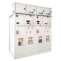
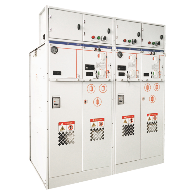
A ring main unit (RMU) is the workhorse of secondary distribution networks—compact, gas‑insulated, and built to connect loads to a ring‑type power supply. But it’s also a device that can kill if treated casually. The SRM‑12 full gas insulated RMU from Changan Electric is designed with an integrated SF6 gas‑insulated system where all 10 kV switches and busbars are sealed in a 3 mm stainless steel gas box, applying silicone rubber cable plugs for full insulation sealing, so that it’s not affected by dust, humidity or small animals. It also incorporates a complete “five‑prevention” interlock system with straightforward operation procedures. This article answers the operational questions site engineers ask most: switching sequence, interlock functions, fault reading, fuse handling, and those subtle maintenance tasks that everyone overlooks until something fails.
How to perform a safe switching sequence on RMU
The core of RMU operation is a three‑position load break switch: ON → OFF → EARTH. The sequence is fixed for a reason—deviating from it puts people and equipment at risk.
Opening the load switch first – why disconnect before grounding
You never close an earth switch onto a live circuit. Doing so creates a bolted three‑phase fault directly to ground. The results are violent—arc flash, equipment destruction, and severe injury to anyone nearby. On a typical RMU, the operating handle for the earth switch is mechanically blocked until the load switch is fully open and the cable side is de‑energized. Always verify the position indicator before proceeding. For powering off, the switch must be put to the ‘earth’ position before access to the fuse chamber is possible.
Closing the earth switch – only after confirming dead
Once the load switch is open, the cable side is isolated but not yet safe to touch. Cables can retain a charge or receive backfeed from other sources in the ring. Before closing the earth switch, verify using a voltage detector that the cable is dead. Then—and only then—insert the operating handle, rotate it to the EARTH position, and confirm the mechanical indicator shows ground. Switching to OFF first, then EARTH, ensures that the circuit is fully de‑energized before grounding.
Accessing the cable compartment – how mechanical interlocks protect
Modern RMUs are designed with five‑prevention interlocks: a mechanical linkage physically prevents the cable compartment door from being opened unless the earth switch is closed. The cable compartment door is mechanically linked to the earth switch position—if the door won’t open, don’t force it. The interlock is telling you the circuit isn’t safe to work on. The SRM‑12 switching device has a complete “five‑prevention” system with straightforward operation procedures, ensuring correct sequential control at every step.
Reverse sequence for re‑energizing
Follow the reverse sequence to re‑energize: open the earth switch (turn counterclockwise until the indication moves to “floating” or off position), then close the load switch. The interlock will release the cable door only after the earth switch is engaged. Operating devices using a handle should be performed by qualified personnel following the procedure and using insulated tools.
What the mechanical interlock actually prevents – three essential functions
The mechanical interlock system is not optional. It‘s the only thing standing between an operator and a deadly mistake. In an RMU, the interlocking mechanism ensures safe sequential operation, preventing incorrect actions like closing a feeder while the earthing switch is still closed or operating under load during maintenance. The SRM-12 features a complete “five‑prevention” system that covers all these functions.
Preventing earth switch closure when the load switch is closed
The mechanical interlock uses physical linkages—rods, pins, or key traps—to block access to the earth switch operating shaft until the load switch is in OFF position. Mechanical interlock ensures correct and reliable sequential operation. If the load switch is closed, the handle won’t fit. This is a fail‑safe design; there’s no override, and there shouldn’t be.
Blocking cable compartment access when the earth switch is open
The cable compartment door is mechanically linked to the earth switch position. If the earth switch is open, the door stays locked. This prevents an operator from entering a live cable compartment—one of the most dangerous scenarios in distribution work. The interlock is part of the comprehensive padlock and passive interlock design for user‑friendly, safe operation.
Preventing fuse‑holder removal under load
On the transformer feeder side, the mechanical interlock prevents the fuse holder from being withdrawn while the load switch is closed. Removing a fuse under load can draw an arc that the fuse holder isn‘t designed to interrupt. The interlock forces you to open the load switch first. If you’ve ever seen a fuse holder blown apart from a hot pull, you understand why this interlock exists.
How to read RMU fault indication – what the gauges and lights are telling you
RMU panels give you three main clues about system health. Misreading them is a common source of wasted troubleshooting time.
Short‑circuit indicator on the panel – what red means
A short‑circuit indicator (sometimes called a fault passage indicator) monitors line current. When current exceeds a preset threshold—usually from a phase‑to‑phase or phase‑to‑ground fault—the indicator triggers a red flag or flashing LED. This tells you the fault is downstream of this RMU. If the indicator is red, investigate the cable section beyond this unit. If it‘s white or off, the fault is elsewhere. The indicator should only be manually reset after the fault is cleared.
Gas pressure gauge for SF₆ – where the needle should be
The SF₆ gas pressure gauge is your early warning system for insulation integrity. On a full gas insulated RMU like the SRM‑12, SF₆ gas is maintained in a sealed stainless steel gas box to provide high electrical insulation strength and arc‑extinguishing performance. If the needle stays in the green zone, the gas is at a safe level. If it enters yellow, gas has leaked, and the insulation strength may have dropped—schedule a leak investigation and gas refill. If it’s in red, do not operate the switch; internal flashover is imminent. A gas box pressure of 0.4–0.6 MPa ensures adequate dielectric strength for safe switching.
Stuck switch position – resistance isn’t always a fault
If the operating handle meets resistance, don‘t force it. A stiff mechanism is often caused by lubricant hardening, especially on units that haven’t been exercised in months. Try opening and closing the switch a few times (with the circuit de‑energized) to work the lubricant. If the resistance persists, the operating mechanism needs maintenance—not brute force. Forcing a stuck switch can damage the interlock linkage, leading to a costly repair.
Below is a quick reference for common RMU operational issues and their likely causes:
| Symptom | Most Likely Cause | Immediate Action |
|---|---|---|
| Earth switch handle won‘t insert | Load switch still ON | Open load switch first |
| Cable compartment door won’t open | Earth switch OPEN, circuit may still be live | Close earth switch, verify dead |
| Fuse blown indicator shows (striker fired) | Transformer or LV side fault | Investigate fault cause before replacing fuse |
| Gas pressure needle in yellow zone | Slow SF₆ leak (seal degradation) | Schedule leak detection and gas refill |
| Operating handle feels stiff | Lubricant hardened; mechanism hasn‘t been exercised | Cycle mechanism (de‑energized) to work lubricant |
| Short‑circuit indicator red | Fault downstream of this RMU | Isolate downstream section before resetting |
When the fuse blows – recognition and correct replacement procedure
The transformer protection fuse in an RMU switch‑fuse combination is a sacrificial device. It clears short‑circuit faults on the transformer or low‑voltage side. When it blows, the correct response is systematic, not hurried.
Fuse blown indication – the striker pin tells the story
When a high‑voltage HRC fuse operates, a striker pin fires out of the fuse body. This pin mechanically trips an indicator on the panel, often a colored flag that drops into view. If the panel shows a blown fuse, don‘t assume the fault is cleared. The fuse did its job—something caused it to blow. You need to find out what. The SRM‑12 F Module uses a load switch with fuse, with fuse ratings up to 125 A and a rated transfer current of 1700 A.
Replacement procedure – isolate before you touch
Replacing a blown fuse starts with isolating the circuit: open the load switch on the transformer feeder, close the earth switch (to discharge cable capacitance), and verify zero voltage at the cable terminals. Only then can you open the fuse compartment cover. Pull the fuse holder out using the dedicated tool. Remove the blown fuse and inspect the fuse base for cracks or carbonization marks—these indicate poor contact that may have caused local overheating. Install a new fuse of exactly the same type and rating. Use the correct torque to tighten the fuse interface to the manufacturer’s specification. Close the compartment, open the earth switch, and close the load switch.
Never bypass the fuse – the safety argument against “temporary fixes”
A blown fuse is a symptom, not the problem. Bypassing it with a copper bar or an oversized fuse converts a manageable fault into a catastrophic one. The fuse is sized to protect the transformer; removing it leaves the transformer unprotected against the next fault. The result is a transformer failure that takes the entire substation offline for weeks. Replace the fuse with the correct rating and investigate the root cause.
Frequently overlooked maintenance tasks on RMUs
Yearly schedules focus on the obvious: gas pressure checks, visual inspections, and interlock verification. But three tasks are almost always delayed—until they cause a failure.
Checking the operation handle for deformation
The operating handle is your only mechanical interface to the RMU. If it’s bent or cracked, it won‘t engage the mechanism correctly. A slightly deformed handle can slip out of the operating shaft at the worst possible moment—mid‑operation. Inspect handles monthly. Replace any that show visible wear.
Annual SF₆ density relay calibration – why calendar matters
The SF₆ density relay is a pressure switch that triggers alarms when gas pressure drops. Over time, its contacts can stick or drift. Electrical maintenance personnel should make SF₆ gas density monitor calibration a scheduled task. In‑service equipment should be tested every 1–3 years, or after major maintenance. If the density relay fails, you won‘t know you have a gas leak until the insulation fails catastrophically.
Cable plug bolt torque – vibration loosens everything
Vibration from daily load cycling slowly loosens cable plug bolts. Loose bolts increase contact resistance, generate heat, and eventually cause a cable failure. Use a torque wrench at each annual inspection to check every cable connection against the manufacturer’s specification.
Extended FAQ – beyond surface questions
Q: Can I operate an RMU load break switch under load?
A: Yes—the load break switch is designed to interrupt rated load current. That‘s what “load break” means. However, do not exceed the switch’s rated current (typically 630 A). Do not attempt to break fault current with a load break switch; that’s the fuse‘s job. And never, under any circumstances, use the earth switch as a load break device—it isn’t rated for it, and the results are violent.
Q: Why is my RMU making a hissing sound, and what do I do?
A: A hissing sound from an SF₆ insulated RMU is almost certainly a gas leak. SF₆ is heavier than air and colorless; by the time you hear it, the pressure has already dropped dangerously. Check the gas pressure gauge immediately. If it‘s in yellow or red, de‑energize the unit if safe to do so, isolate the circuit, and call for maintenance. Do not operate any switches until the pressure is restored.
Q: What is the difference between an RMU and a regular circuit breaker?
A: An RMU uses a load break switch for normal switching and a fuse for overcurrent protection. A circuit breaker (VCB) uses a vacuum interrupter and a protection relay, allowing multiple operations under fault conditions. RMUs are smaller, simpler, and more economical for transformer feeders. Circuit breakers offer selectivity, automation, and remote control. For a standard distribution transformer, the RMU‘s fuse‑switch combination is a proven, cost‑effective solution.
Q: Is an oil‑insulated RMU still available, and how does it compare to SF₆?
A: Yes, oil‑insulated RMUs are still manufactured, though SF₆ and solid‑insulated (environmentally friendly) types are now more common. Oil units are typically older and require more maintenance—oil sampling, dielectric testing, and periodic filtration. SF₆ units like Changan’s SRM‑12 are fully sealed, requiring no gas refilling under normal conditions and no regular maintenance other than fuse replacement after a fault.
How Changan Electric‘s SRM-12 supports safe daily operation
The SRM‑12 ring main unit from Changan Electric is built around three operating principles: safety, simplicity, and serviceability. Rated for 10 kV at 50/60 Hz, the unit uses full SF₆ gas insulation with a stainless steel gas box welded from 3 mm plate, which eliminates the need for regular dielectric testing or oil handling. The main busbars are rated at 630 A (1250 A optional), with a short‑circuit withstand of 20 kA for 3 seconds and lightning impulse withstand voltage of 75/85 kV. The SF₆ gas pressure is maintained in the range of 0.4–0.6 MPa—sufficient to preserve the dielectric strength that enables the switch to safely make and break load current.
The switching device incorporates a complete “five‑prevention” interlock system with straightforward operation procedures, guaranteeing correct sequential control at every step. The front panel provides clear, unambiguous indication of switch position (ON/OFF/EARTH) and gas pressure status, so the operator knows exactly what state the equipment is in before touching the handle. The fully sealed design ensures that the switch is not affected by external environmental factors such as dust, humidity or small animals, reducing the risk of unexpected failures.
For distribution systems, ring power supply, and biradial networks in factories, residential high‑rise buildings, and prefabricated substations, the SRM‑12 provides receiving, distribution and protection functions in a compact footprint. Before you commit to a large‑scale RMU rollout or replace aging oil units in your network, run through a site evaluation—confirm your fault current levels, verify the required voltage class, and train your team on the correct switching sequence. The difference between a unit that operates safely for decades and one that fails at the first fault is often just a matter of discipline and documentation.
Need technical support for RMU operation or a quote on the SRM‑12 series? Contact Changan Electric with your system voltage (10 kV or higher), fault current level, and the number of ring units required. Their engineering team can provide switching sequence training materials, interlock verification checklists, and custom panel configurations for your substation layout.