Home
Products
Distribution Transformer
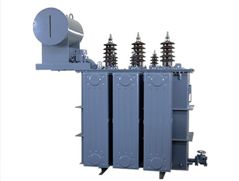
Oil Immersed Transformer
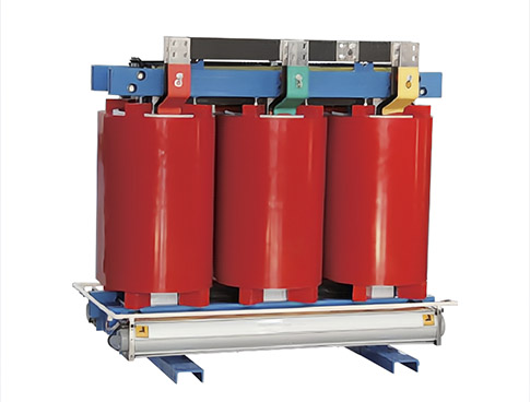
Dry Type Transformer
Switchgear
Low Voltage Switchgear
Ring Main Unit
Air Insulated Switchgear
Prefabricated Substation
EU Type Prefabricated Substation
Transmission Line Products
Fuse Cutout
Composite insulator
Surge Arrester
Overhead Line Fittings
Voltage Vacuum Circuit Breaker
Outdoor Circuit Breaker
Indoor Circuit Breaker
Current&Voltage Transformer
Indoor Current Transformer
Outdoor Current Transformer
Special Current Transformer
Indoor Voltage transformer
Outdoor Voltage transformer
Low Voltage Products and Systems
MCB
RCCB
RCBO
AFDD
Isolator Switch
Molded Case Circuit Breaker-MCCB
Air Circuit Breaker-ACB
Magnetic contactor
Low Voltage Current Transformer
Fuse
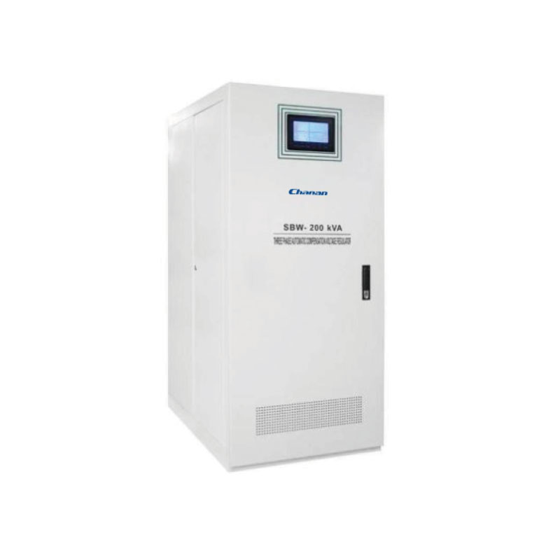
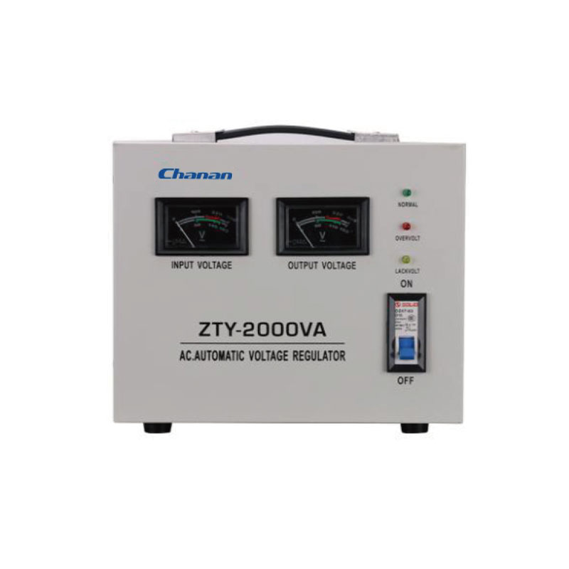
Voltage regulator
Service
Solutions
Download
Exhibition
Blog
About CHANGAN
Company Profile
Video
Contact Us
English
English
Pусский
Español
404:The request page was not found
Maybe you'll be interested in some of our other products
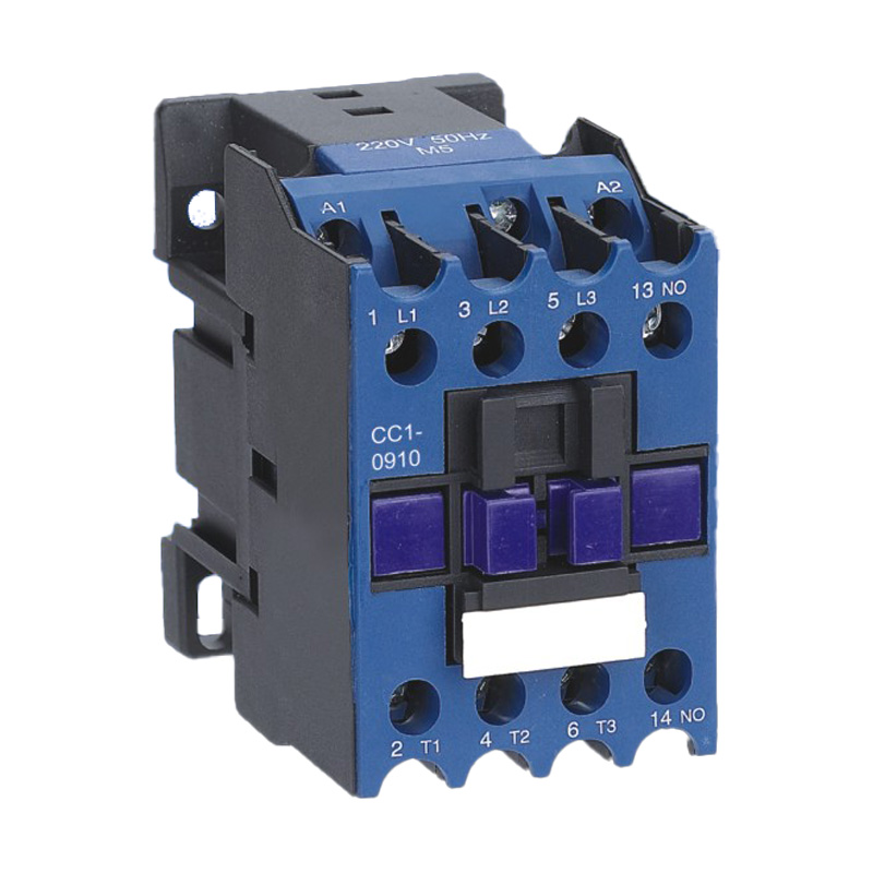
CC1 AC Contactors (9A-95A) | Reliable Circuit Control
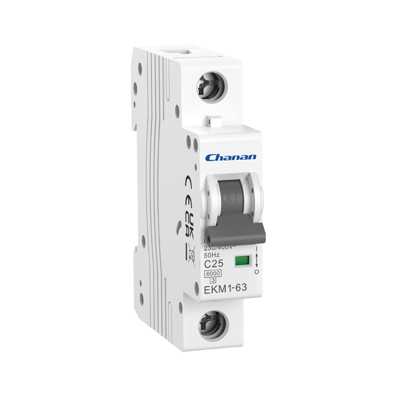
EKM1-63 6kA Miniature Circuit Breaker MCB
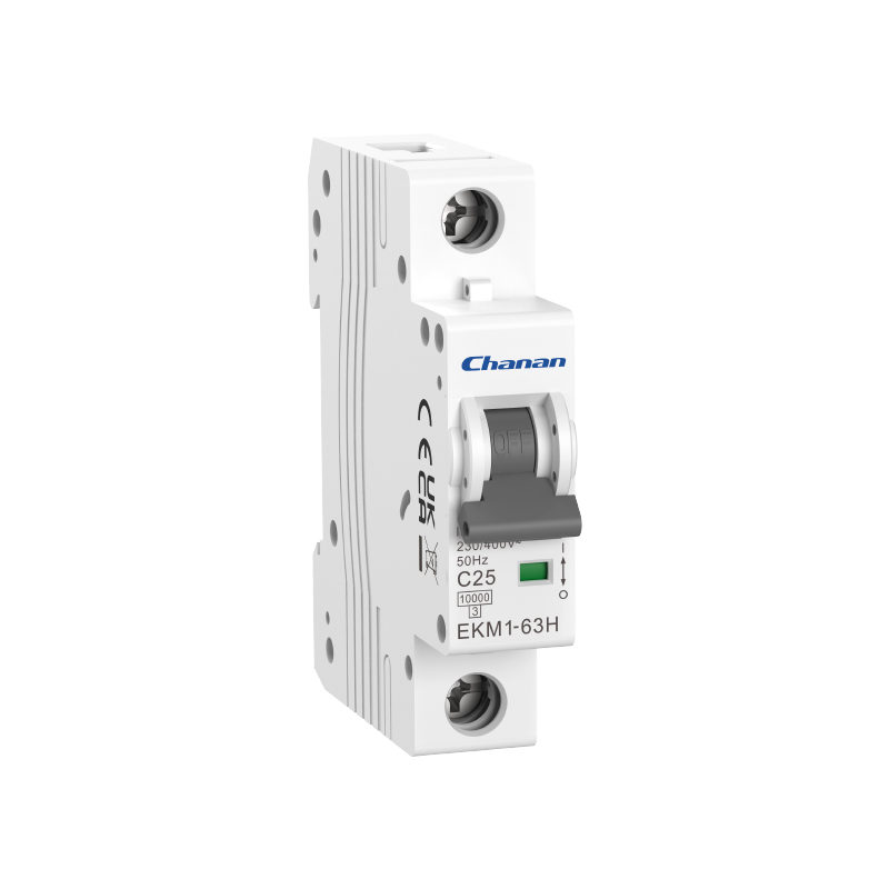
EKM1-63H MCB 10kA Miniature Circuit Breaker
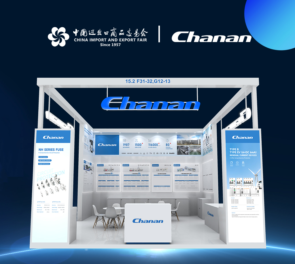
Join Changan Electric at the 135th China Import and Export Fair in Guangzhou
Characteristics and advantages of dry type transformer
What is difference between dry type transformer and oil type transformer?
SBW Automatic Three phase compensation Voltage regulator
TND AVR Single phase Automatic Voltage regulator
We value your privacy
We use cookies to provide you with a better online experience, analyse and measure website usage, and assist in our marketing efforts.
Accept All