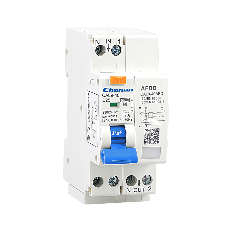
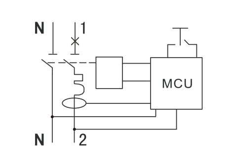
CAL9-40AFD is 1P+N(Pole N could be ON/Off arc fault detection devices with integrated RCBO in 6kA breaking capacity, with rated current up to 40A and Sensitivity optional 10, 30, 100, 300mA. LED arc fault indication (During standard operating mode (toggle in ON position), the LED is green. When the toggle is on OFF position or when a fault occurs, the LED is OFF), gray test push button to verify the correct functioning of residual current device. In only 36mm width, they provide protection against arc faults, overload short-circuit and earth fault currents.
| Standard | IEC61009-1, IEC62606 |
| Mode | Electronic |
| Type | AC, A |
| Rated current In | 6,10,16,20,25,32,40A |
| Poles | 1P+N (Pole N could be On/Off) |
| Rated voltage Ue | 240V~ |
| Insulation voltage Ui | 400V |
| Rated frequency | 50Hz |
| Rated residual operating current(I△n) | 10,30,100,300mA |
| Break time under | ≤0.1s |
| Rated breaking capacity | 6,000A |
| Energy limiting class | 3 |
| Rated impulse withstand voltage (1.5/50) Uimp | 4,000V |
| Dielectric test voltage at ind.Freq. for 1min | 2kV |
| Thermo-magnetic release characteristic | B, C |
| Electrical life | 4,000 Cycles |
| Mechanical life | 10,000 Cycles |
| Contact position indicator | Yes |
| Protection degree | IP20 |
| Ambient temperature | -25℃ to +40℃, Max.95% humidity |
| Terminal connection type | Cable/Pin-type busbar |
| Max. terminal size for cable | 16mm2 |
| Max. tightening torque | 2.5N.m |
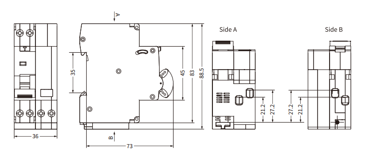
| Mounting | Mounting on 35mm DIN rail |
| Connection | From top |
Send us a message if you have any questions or request a quote.Our experts will give you a reply within 24 hours
and help youselect the right valve you want.